Installing the Valve TrainThe first step was to degree the cam. To do this, we set up a travel dial indicator on the number one piston and turned the crankshaft until the piston reached top dead center. We then installed a degree wheel on the crankshaft with a wire pointing to 0 degrees on the degree wheel. |
||
| We then installed the lifters for the number one cylinder and setup
the travel dial indicator so that we could measure the lifter travel as
we rotated the crank. The lifters rose and fell within one degree of
spec which is easily within our measurement error.
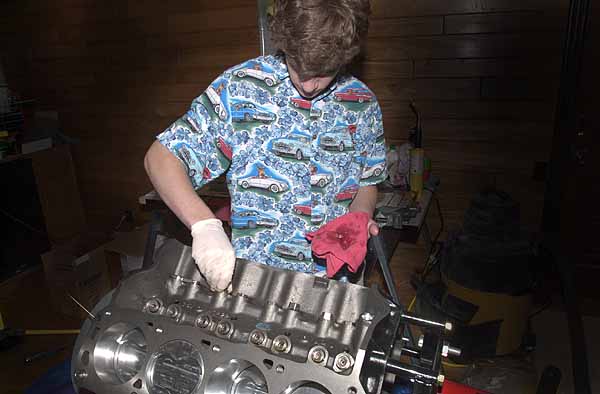
Our next step was to check the valve clearance. We decided to use the "clay on the piston" approach. We filled the |
||
| piston bowl with clay and rubbed a little oil on top so that the valves wouldn't stick to it. We then installed the head with a few bolts to hold it in place, and installed the pushrods and rockers for the number one cylinder. After a couple rotations of the crank, we disassembled everything to take a look at the valve indentations in the clay. As can be seen in this photo, even without the head gaskets in place, we clearly have plenty of clearance. | ||
 |
The next step was to install all the lifters and the lifter retainers
which prevent the roller lifters from rotating on the camshaft. The
lifters had been soaking in an oil bath for a few days which is
recommended by some engine builders (although not by all).
With the lifters in place, we installed the cylinder head studs. Since the outside studs protrude into the cooling channels, these were coated with thread sealer before threading them into the block. |
|
| Once all the studs were installed, we put on the head gaskets making sure they were correctly oriented so that we did not block any cooling channels. | ||
| The cylinder heads then slipped on over the studs. We hand tightened
each of the nuts, then proceeded to torque them down to spec. Starting
with the center nuts, all bolts were torqued to 25 ft-lbs, then to 50,
then 75, then 90. The outside, shorter studs, were then torque to 100
ft-lbs.
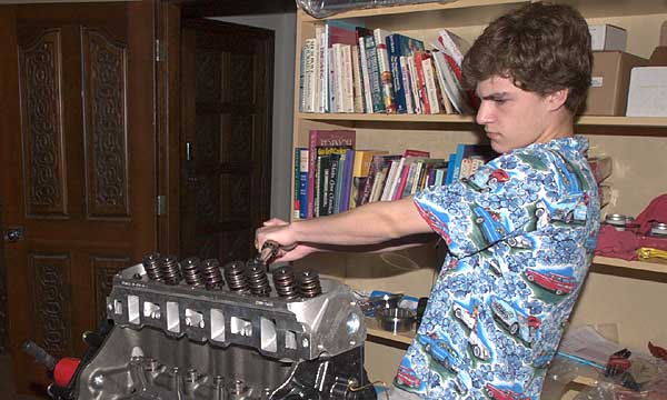
Once the heads were one, the next step was to install the rockers and adjust the valve lash. The rockers are tightened down |
 |
|
| so there is no wobble in the rockers, but before there is any compression of the hydraulic lifters. The rockers are then tightened down another 1/2 to 3/4 turn so that the lifters are about half compressed. This is done one cylinder at a time with the crank rotated so that the cylinder is at top dead center (so that both valves are completely closed). | ||