July 2002

July 4 - Happy Independence day. Over the past several days, we've been designing parts that we will need to be custom machined. We had been planning to build seat mounts that would allow the seats to slide forward and back, but we finally decided that this would force us to add too much height to the seats. So we designed two mounting blocks - one for the rear side of the seat and another for the under the front bottom. These have threaded holes in the bottom which will be used to bolt the seats to the floor from below. To move the seats, we'll have to remove four bolts and move the seats to other holes.

We also designed an alternator mounting scheme. We will use a long bolt through the alternator into the head for one end. We designed a spacer to be used between the alternator and the head to hold it the correct distance out. We also designed a bracket that will mount between the alternator and water pump to keep the bolt from flexing.  
For the bottom of alternator mount, we are using a turnbuckle with rod-ends mounted to the water pump with a spacer. This will allow us to adjust the alternator position somewhat to get proper belt tension.

The Pro-5.0 shifter we bought did not come with a shift lever so we are also having something machined to use for this. We decided we wanted a relatively short throw with a slight forward cant. A 1/2" threaded stud will connect the lever to the shift knob. A shoulder nut will hold the leather boot snugly against the shift knob.

  Another issue we've been pondering for a while is the throttle control. The eight throttle bodies on the TWM induction system create a large load with high inertia for the throttle cable. After hooking this up to the throttle pedal, we found it to be very sluggish. We could probably add a heavier spring to the butterflies to make them close faster, but this would further increase the already heavy pedal force required to open them.
The solution we are now pursuing is electronic throttle control. This is similar to the system used in the new Lexus cars and the new Corvette. Instead of a physical linkage between the gas pedal and the throttle bodies, the gas pedal just has a spring and a position sensor. A motor is used to control the position of the throttle butterflies. An electronic circuit controls the linkage. This will give us lightning fast throttle control with relatively light pedal effort.

Electronic throttle control opens up all sorts of possibilities for control that are not possible or practical with a mechanical linkage:

bulletDifferent throttle mappings for performance and casual driving.
bullet"Valet mode" which limits throttle input.
bulletCruise control.
bulletAutomatic downshift rev-matching.

Here's some more details about what we're planning.

July 15 - We haven't done a lot of work over the past week due to other commitments, but we've made some progress.

  JBL sent us updated control arms for the anti-roll bars. The one on top is the new one for the front. We're waiting for two more rod-ends with studs to
install the back control arm.

We also made some brackets to mount the Accusump above the front anti-roll bar actuator. There's not a lot of room in the JBL engine bay but we're pretty sure we can get everything in that we need to.


Here's a photo showing our fuel pressure sender. We mounted the sender on a custom bracket that attaches to the distributor. The distributor is actually required only to drive the oil pump since the ignition is handled by the Electromotive and is controlled by a crank position sensor. So we stripped as much of the guts from the distributor and machined a custom aluminum cover as shown here.

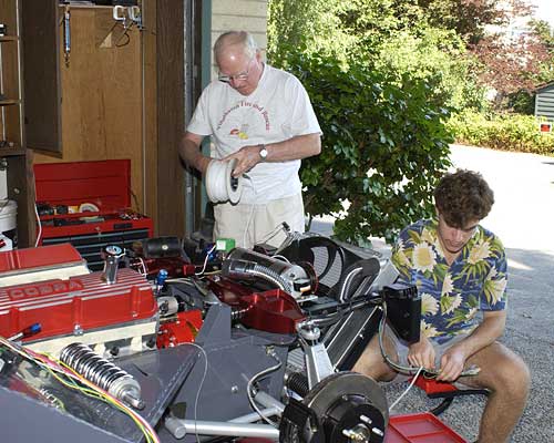
Scott has been working a lot 
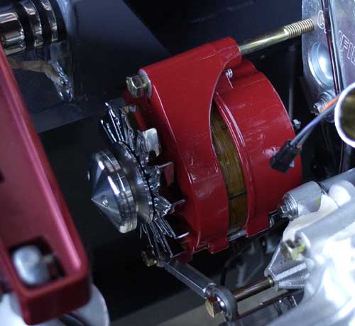
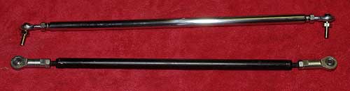
on the electrical system and has wired up and tested the anti-roll bar linear actuators, the radiator fan, the head lights (including high/low 
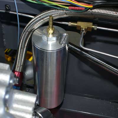
beam switching), the fuel pump controller, dash lights and gauges, horn 
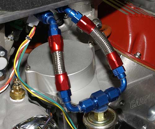
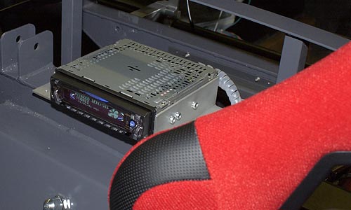
(it's LOUD), and accusump. He also wired up the radio, but it doesn't seem to be working yet - still debugging.
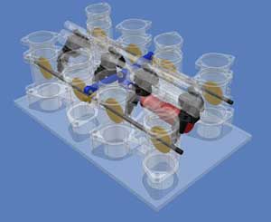
I designed a circuit for the LED bar graph to indicate the position of the linear actuators and Scott did the PC layout. We found an online company that does inexpensive PC fabrication and should have the PC board by the end of the week.

Scott's been working on mechanical drawings for our throttle control while I've been working on the control electronics. I'll post more details in a couple of days.

July 19 - Scott spent the day at Portland International Raceway taking the Advanced Driver Safety course at Prodrive. He's also signed up for their Introduction to Road Racing course later this summer.

But before heading to Portland, Scott was very busy working on the throttle motor mount design. Scott modeled the TWM throttle bodies using Autodesk Inventor and then designed the throttle control motor mount and linkages. This image shows where the motor (red) and linkage (blue) fits but doesn't show the mount. Here are all the details.  
 

In the meantime, I've been working on the control circuitry for the motor. Here's a basic block diagram. Click on the image for a larger view.

The control logic will be built on two small PC boards - one with the microcontroller implementing the throttle functions and the other with the throttle motor control and fault detection circuitry.

We decided to add a few more functions to the throttle control logic since they were easy to add. We added a four button keypad and a 2x20 character vacuum fluorescent display to support these functions.

Since we never really had an ignition key, we decided to add a simple electronic lock. When you switch on the ignition, the VFD will display "LOCKED" and the ignition system will be disabled. When the correct numeric sequence is entered on the keypad, the VFD will display "READY" until the car is started.

Once the car is started, the VFD will display various information about engine and throttle function (including thermal sensors, throttle mapping, etc.). We will also enable a way to change between several different throttle maps.

We've also made a change to the "failsafe" logic of the throttle controller. Instead of disabling the ignition if a fault is detected, the auxiliary rev limiter will be enabled which will slow the engine down to approximately 2500 rpm by disabling cylinders (spark and fuel injection). This will provide a less abrupt shut down that will be safer if the throttle were to fail during a high speed turn.

July 25 - Scott has continued to refine the mechanical design of the throttle controller and we hope to bring the drawings to a local machine shop tomorrow. Scott's done a great job on these drawings. I'll post them soon. My father has been visiting this week and helping with the car, so we've made a lot of good progress.  
  We have almost completed the oil plumbing - just waiting for a fitting from AN Plumbing to attach the oil filter to the block adapter. Andy (our source for much valuable info on building the JBL) recommended that we look at the Canton inline filter. This solved a lot of our space problems in the engine bay, but we'll have to get a bracket machined to hold the filter.
We also finished most of the radiator plumbing. We're using Coolflex hoses which allows us to shape the hoses to meet the unusual contours of our specific installation. They also look great!

We drilled a hole through the front chassis plate to pass the hose from the lower radiator port to the water pump. This hose must be bent to clear the steering shaft and the anti-roll bar.

 
  The radiator overflow tank is wedged in on the left side of the engine bay near the oil filter and plumbing. I'm not sure how we would have fit this if we used a conventional remote mounted oil filter. Since this photo was taken, we've cleaned up the oil line routing and wrapped the electrical wiring with coiled wire wrap. It looks very clean.
Scott's also been continuing to work on the electrical system and got the blinkers and parking lights working and the wiring more permanently installed. We had fun getting the horn button installed on the steering wheel. We had already mounted the Sparco wheel adapter to the steering column and had to remove this to attach
the wiring. The adapter does not come off easily. My father came up with the idea of drilling a couple holes in some aluminum bar stock and use bolts into two threaded holes in the adapter to act as a puller. This finally worked and we got the horn switch installed.  
July 26 - Scott finished the drawings for the throttle control motor mount last night, so we made a visit to a local machine shop (run by Mike Birdwell) that one of my friends recommended. Mike and his son were bright and enthusiastic with a nice shop and were excited by Scott's design. Mike promised to get back to us in a couple days with an estimated cost and time.
  We got the stereo in the car working, so now we can listen to tunes while we work. Our stereo is mounted in the back of the passenger compartment between the seats. We had planned to have this totally concealed and operated by an IR remote control.

However, Scott hooked up the Xantech IR repeater incorrectly, so we had to deal with that burnt electronics smell for a few hours. After dismantling the Xantech, we determined that we had just burnt a couple PCB traces which were repairable. But in the end, we decided that we'd be better off without the IR repeater and could just put a red plexiglass window in front of the stereo so that the remote could be used without the repeater.

Next Month - more progress on the throttle controller, finishing up the electrical wiring and plumbing.